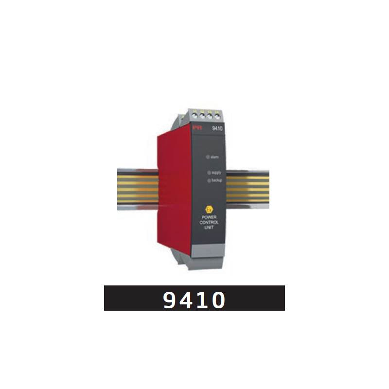
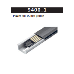
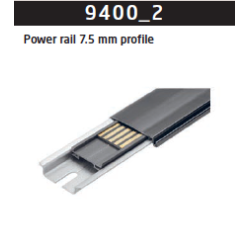
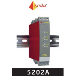
The power control unit detects errors from any of the devices mounted on the power rail and transmits a collective alarm to the control system via the internal status relay.
Optional connection of two power supplies - a primary supply and a backup supply.
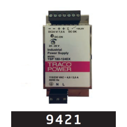
Redundant supply for the power rail can be obtained by mounting two 9410 devices connected to 2 separate power supplies (e.g. PR no. 9421).
Technical characteristics
The status relay will be energised when the following three conditions are met:
Supply voltage is present on pins 31 and 32.
Backup supply voltage is present on pins 34 and 33. (If the backup supply is not in use, a jumper must be placed between pins 32 and 33 - the jumper is delivered with the device).
There are no error messages from the devices connected to the power rail.
When a collective alarm is activated via the power rail, the status relay in the 9410 will be de-energized (pins 11, 12 and 13).
Two green front LEDs indicate connection of supply and backup.
Current: 4 ADC
Power, max.: 96W
Status relay: 1 x SPDT, AC: 500 VA
Voltage: 21.6...26.4 VDC
Technical Specifications
Ambient temperature: -20...+60°C
Channels: 1
Isolation, test: 2.6 kVAC
Max. required power: 96W
Output ripple: Same as input
Programming: No
Short circuit protection: Yes
Approvals
ATEX, Zone 2: Yes
CCC / KCs: Yes
CSA, Zone 2 - DIV 2: Yes
DNV: Yes
EAC: Yes
FM, Zone 2 - DIV 2 : Yes
IECEx, Zone 2: Yes
INMETRO, Zone 2: Yes
UKEX, Zone 2: Yes
UL 61010 / 508 / 913: Yes/No/Yes
Application guide
96 W power rail connector unit: Yes
Collective status signal monitor: Yes
Internal fuse: Yes
Mounting in Zone 2 / DIV 2: Yes/Yes
Redundancy power rail function: Yes
New
Comments (0)
No customer reviews for the moment.
Your review appreciation cannot be sent
Report comment
Are you sure that you want to report this comment?
Report sent
Your report has been submitted and will be considered by a moderator.
Your report cannot be sent
Write your review
Review sent
Your comment has been submitted and will be available once approved by a moderator.