
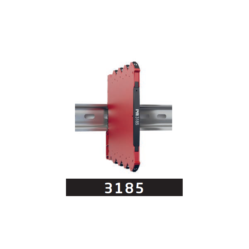
In a retrofit scenario, a ground loop disturbs the active 4…20 mA signal sent by a separately powered transmitter to a passive PLC input. The PR 3185A1 galvanic isolator from PR electronics is added between these devices. The check starts with the signal path and the energy source for the device being added to the loop.
Power comes from the input loop
PR 3185A1 is powered from the input loop and requires no auxiliary supply. The transmitter powers the isolator input, while the isolator's active output supplies current to the passive PLC input. Identify this sequence clearly in the wiring diagram.
The device nominally reproduces the 4…20 mA signal at a 1:1 ratio. Electrical separation between input and output interrupts the ground loop along the signal path. The 3185A1 variant has one channel and occupies 6.1 mm on the DIN rail.
Check voltage margin and output load
The absence of an auxiliary supply does not remove the need to check power requirements. The signal source must cover the voltage drops across the isolator, cables and load. At the output, the total permitted load is no more than 600 Ω.
Before adding the device to an existing loop, compare these requirements with the wiring diagram and connected equipment. Matching the 4…20 mA range must be accompanied by a check of the available voltage margin.
Acceptance checks
Document the input loop supply, active output and passive PLC input. Check nominal signal repetition and the connected load, then confirm that the source covers the voltage drops along the complete path.
Source: ATSEN LinkedIn post, published on 22 October 2026.