
Connecting a Pt100 sensor to a PLC with a 0…10 V input requires checking the complete measurement chain. The sensor provides a resistance that depends on temperature, while the automation system needs the voltage corresponding to the selected range. The ATSEN scenario focuses on three points: the sensor, conversion and scaling.
The sensor and signal conversion
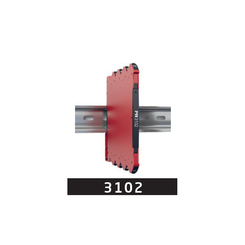
PR 3102 from PR electronics accepts a 2-, 3- or 4-wire Pt100 sensor. It provides the measuring current and converts the sensor resistance into a 0…10 V signal proportional to temperature.
Before wiring, identify the sensor's connection arrangement and follow its path to the converter. Recognising the Pt100 designation alone does not complete this check: the actual connection must match the equipment used in the measurement chain.
The temperature range and PLC input
DIP switches select the 0…10 V output and the precalibrated temperature range. Configure the same voltage-to-temperature relationship in the PLC. The presence of a voltage does not by itself confirm that the value displayed in temperature units is correct.
The converter uses a separate 24 V direct current (DC) supply. The PLC voltage input must have an impedance of at least 10 kΩ. For panel integration, the housing occupies 6.1 mm on the DIN rail.
The acceptance check
During commissioning, compare the sensor temperature with the value displayed in the PLC and check the relationship to the selected range. Follow the sensor, converter configuration and automation scaling in sequence. This checks the result of the complete chain, beyond merely confirming a voltage at the PLC input.
Source: ATSEN LinkedIn post, published on 15 October 2026.