
A transmitter provides a 0…10 V DC voltage signal, and the measurement must be integrated with a PLC. Choosing between direct connection and conversion to 4…20 mA starts with the available input type and a check of the electrical conditions along the signal path.
When direct connection is possible
Direct connection requires a compatible voltage input. Before making the connection, check the load, electrical reference and PLC input limits. This arrangement uses one fewer device when the compatibility requirements are met.
The 0…10 V range must match the scaling in the automation system so that the displayed value corresponds to the measurement. Base the decision on the actual input and wiring diagram for the installation.
Conversion for a PLC current input
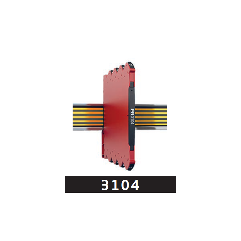
If the available input is a current input, PR 3104 from PR electronics allows 0…10 V to be converted to 4…20 mA. The device provides galvanic separation between input, output and supply, with ranges configured using DIP switches.
In the presented example, the transmitter has its own power supply. PR 3104 is supplied separately at 24 V DC. The converter's active output supplies current to a passive PLC input that does not power the loop. The total load, including cables, must be no more than 600 Ω.
Checks before commissioning
Match the DIP-selected ranges to PLC scaling. Follow the transmitter supply, converter supply and output circuit separately. Record the selected arrangement along with its checked ranges and connection requirements.
Source: ATSEN LinkedIn post, published on 26 October 2026.