
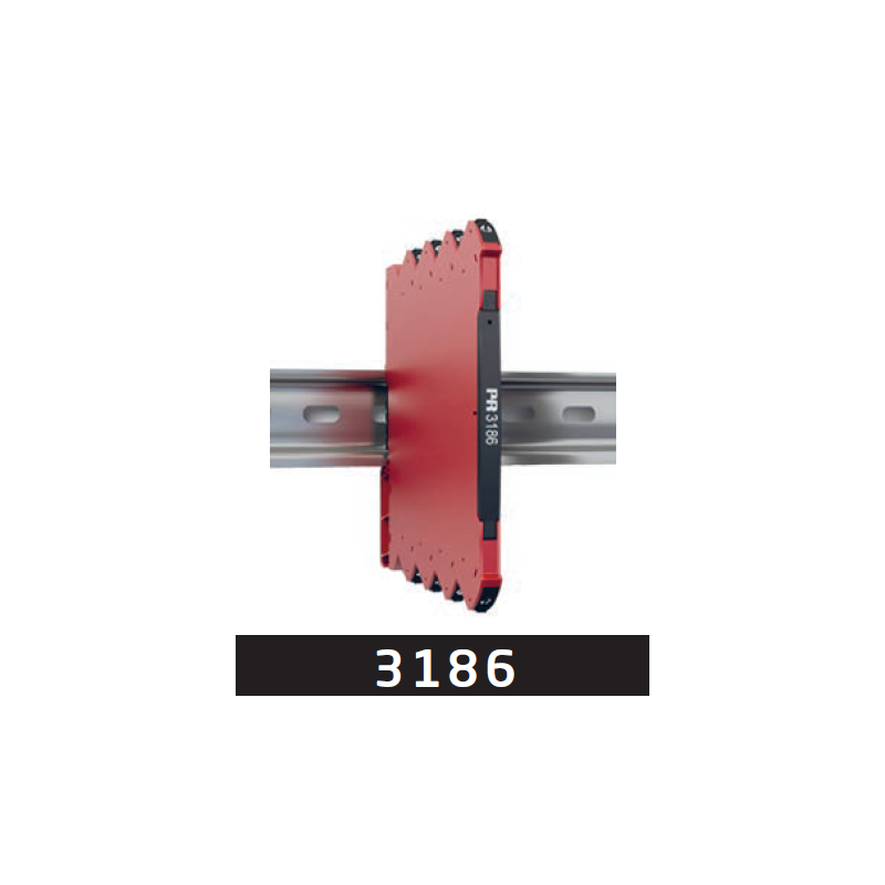
Two devices can use the same 4…20 mA range without automatically forming a working loop. Connecting to the PLC also requires identifying which equipment supplies power to each circuit. The ATSEN example follows this check for the PR 3186B1 galvanic isolator from PR electronics.
An active input signal, repeated 1:1
PR 3186B1 receives an active 4…20 mA signal supplied by the signal source and reproduces it 1:1 at the output. Electrical separation between input and output interrupts the ground loop along the signal path.
The presented variant has one channel and occupies 6.1 mm on the DIN rail. Repeating the signal preserves its range; checking the power supply remains a separate requirement from matching the 4…20 mA range.
The passive output is powered from its loop
The device has a passive output, and the isolator is powered from the output loop. It can connect to an active PLC input that supplies power to this loop. The wiring diagram should make clear which equipment provides power on each side of the isolator.
At the device terminals, 6…35 V direct current (DC) must remain after voltage drops across the load and cables. In the input circuit, the signal source must accommodate a maximum voltage drop of 3 V across the isolator. Check these two conditions separately.
Checks before commissioning
Document whether the connections are active or passive and the voltage budget of each circuit. During acceptance, follow both signal repetition and the output loop supply. A 4…20 mA label alone does not confirm these conditions.
Source: ATSEN LinkedIn post, published on 21 October 2026.