
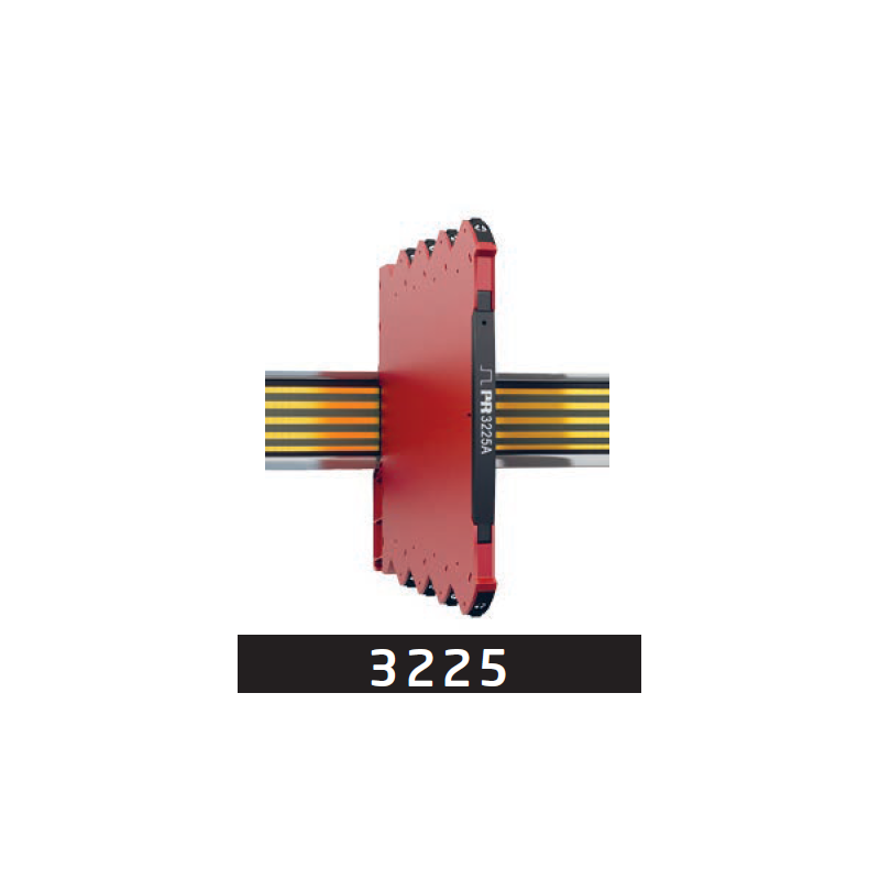
A PNP sensor monitors a rotating shaft and transmits pulses, while the available PLC has a 4…20 mA input. For the automation system to display rotational speed correctly, signal conversion must match the number of pulses per revolution and the scaling in the PLC.
Frequency conversion and circuit separation
PR 3225A-N from PR electronics converts pulse frequency into 4…20 mA within the configured range. The input, output and supply are galvanically separated, with no direct electrical connection between these three circuits.
Configuration is available through DIP switches or a detachable display connected using the optional ConfigMate adapter. Document the selected range so that the same relationship can be followed when configuring the PLC's analogue input.
Sensor supply and PLC input
The module is supplied through its terminals at 24 V direct current (DC). In the presented scenario, it also powers a compatible PNP sensor at 12 V, drawing no more than 23 mA. Check that the sensor is compatible with these conditions before connecting it.
The active output supplies current to a passive PLC input. The total permitted load is no more than 600 Ω. Identify the module supply, sensor supply and 4…20 mA signal path separately in the wiring diagram.
What to document and check during acceptance
Match the three values that determine the displayed reading: pulses per revolution, the configured frequency range and PLC scaling. During the acceptance check, compare the reference rotational speed with the displayed value. If they do not agree, follow these three settings before treating the conversion as verified.
Source: ATSEN LinkedIn post, published on 20 October 2026.