
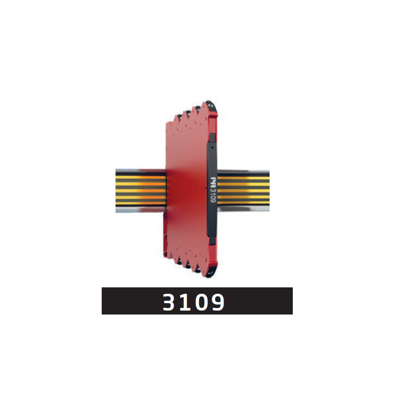
When the same pressure must be monitored in a PLC and a recorder, each receiver needs a signal compatible with its input. This design example starts with a separately powered transmitter with an active 4–20 mA output. PR 3109 from PR electronics sends the measurement information along two galvanically separated paths.
12 mA in, nominally 12 mA at each output
With the input and both outputs configured for 4–20 mA using the DIP switches, each output nominally reproduces the input current. An input of 12 mA therefore gives a nominal 12 mA at each output; the current value is not divided between the two destinations. These settings define the example and must be checked on the installed device.
The active outputs supply current to passive inputs on the PLC and recorder. The receivers do not power these loops. The input, each output and the power supply are galvanically separated, allowing information to pass without a direct electrical connection between the circuits.
Check each signal path separately
PR 3109 requires a separate supply, for example 24 V direct current (DC). The permitted total load is ≤ 300 Ω on each output. Check this condition for each circuit, together with the requirements of its connected input.
During commissioning, confirm the ranges selected by the DIP switches and the scaling of both receivers. Comparing both paths at the same input signal checks their current values and displayed pressures. To display the same pressure, the PLC and recorder must interpret the 4–20 mA range consistently.
Source: ATSEN LinkedIn post, published on 13 October 2026.