
ATSEN post dated 15.09.2026
The sensor delivers −1…+1 V, while the PLC expects 4…20 mA.
What output value should you check when the input is 0 V?
For direct linear scaling, the illustrative calculation is:
−1 V → 4 mA | 0 V → 12 mA | +1 V → 20 mA.
At 0 V, we are halfway through the input range and therefore halfway through the output range too. The midpoint provides another reference for checking scaling in the PLC. This is a configuration example, not the device's default setting.
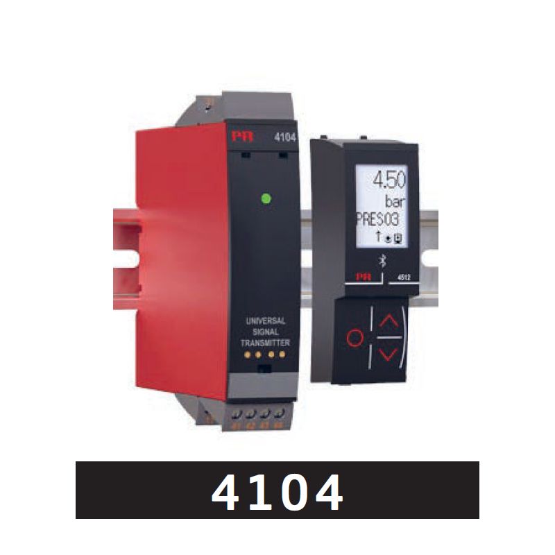
PR 4104 from PR electronics supports:
• conversion of unipolar and bipolar signals, including from ±1 V to 4…20 mA;
• adapting loop power through active or passive inputs and outputs;
• configuration and diagnostics with a detachable local digital display, available as an accessory.
How do you check the midpoint of the scaling between the sensor and PLC in practice?
Details and availability:
PR 4104
For resellers and integrators: the discount is activated manually after account creation, contact and confirmation of your status.
hashtag#AnalogueSignals hashtag#SignalConditioning hashtag#IndustrialAutomation hashtag#PLCIntegration
Source: ATSEN — LinkedIn